TRUTH IS ONLY IN THE THOUGHT OF THOSE WHO DO NOT UNDERSTAND.
In the beginning was water. Or was it carbon? We don't know this anymore. Our history concentrates on carbon. C stands for carbon. O, for our actions when we took the wing out of the vacuum bag. Co2 stands for much carbon and many O's.
Easy was only the beginning and we were beginners in the subject of tailless gliders when we began four years ago. We believed that we could transfer our f3b experience without any breakage into the new era of flying wings.
1000 times touched, 1000 times nothing happened. (A song in the German hit parade about 1985)
 In the meantime it has happened, but as the saying goes, good things will take some time.
Why should we discuss our beginnings. we have come some way. In the early days we were cheeky enough to publish our first flying wing experiences. The report on our Pirx and the Just In Time series haven't been without consequences. Everybody who constructed to our plans, we would like to express our appreciation to this day, you were not so wrong.
In the meantime it has happened, but as the saying goes, good things will take some time.
Why should we discuss our beginnings. we have come some way. In the early days we were cheeky enough to publish our first flying wing experiences. The report on our Pirx and the Just In Time series haven't been without consequences. Everybody who constructed to our plans, we would like to express our appreciation to this day, you were not so wrong.
I find it very difficult to write this report. I have been trying to construct F3b flying wings for 3 years now. How easy it would be to report about a conventional model or a flying wing if it wasn't supposed to be also a good model for f3b. For two years now I have been a member of the b group for f3b. Please believe me, it is not fun anymore. You are always flying against the world champions or those you believe will be the next world champions. Not a very good position for experiments, but what the heck.
An underdesigned winch and too much respect. In short the psychology. I thought we were prepared for all situations. Business as usual. 19th on the last comp in 1988 will not change anything on that fact. At this point I would like to say thank you very much to all the B kader who told us in honesty that if we would achieve the same launching height, as with conventional airplanes the situation would be much different.
In my position of a author and not a publisher I can afford from time to time to give a sharp comment. I think that flying wings with respect to special tasks, flying for time or on the slope have been competitive for a long time. Especially the swept flying wing. It brings from its construction maneuverability and high speed which will encourage you to fly astray. To go the f3b or an other category. It consists of an aircraft with good all around capabilities. Right from the beginning we wanted more. We wanted less sink, higher glide angles and good high speed characteristics. With that the noose was getting tight.
A model like the Pirx, which was designed for minimum sink could very quickly be seen in contest, for example the Versmold cup. No trouble for such a design. But how could be get better distance and keep it stable for high speeds. In other words the last three or for years we would have liked to concentrate on aerodynamics. But instead at the same time we had to construct against the other problem of the winch. I confess we have not been able to compete on that subject. Our recent Lucas m50 winch has too much power and not enough rpm . Is it the fault of the flying wing? I don't think so.
1987 was the year of the big break through. In the winter Just in Time 2 was created. A fully symmetrical HQ 0.0/9 was selected to gain control of the various swinging oscillations experienced. 1 degree dihedral from half wing span was considered to be the basis and was considered a reasonable figure for speed runs. Washout on the trapezoidal tips was selected to gain better behavior on the launch.
JIT 2 was built in 6 variants, with different winglet configurations, from a backward position and small to rounded bow were compared in experiments. Today we know that the most suitable type wasn't taken into consideration. Typical construction blindness.
The 1987 season was completed with satisfaction by the flying wing opposition. 1st place Uelzen, 1st place Versmold and 1st place Zannonia Cup in Austria. Also club competitions against conventional Aircraft were also satisfactory. Handling and flying characteristics didn't reach the high level in those days. We must remember that with a total weight of 3.2 kilograms it was a fair lump of aircraft that got catapulted into the air. By the way, the high weight of the flying wing was not a problem as we have found out in the meantime. As you can see we have work in progress with a lot of dead ends.
The hour of truth. The B Kader comp in Lunen. Low winds of 15 m/s and gusts slightly above. Our A model falls to pieces on the first day. Luckily nobody saw it. We were enthusiastic. The new winch seemed to really deliver some power. When we flew the B model on Saturday on a distance task. All control surfaces were ripped off. Our enthusiasm was dampened. What happened?
At the catapult action at the end of the launch, large oscillation has occurred on the wing and Helmut Quabecks comment was "The winch is hitting back". Why on the small flying wing? At least now we had the opportunity to cut our JIT's with the help of a circular saw into small pieces and bring them to show to the Kaltenkirchen flying wing seminar in the beginning 1988 for demonstration purposes. The end result was that the progress we achieved was noticed on the both at the negative and positive experience levels.
The way the Cmo=0 characteristics were showing the effect that we hoped for . As well as the minimized winglet washout.
Stall characteristics and just stability were satisfactory . But it was getting worse. The repaired B model all of a sudden started spinning like a prop on the winch line. Why did the wing stiffness problem come up again? We tried to solve it for the last two years by using one piece wings.
Because I don't want to write a 40 page report, without the best materials, like cloth and epoxy and subtle diagonal strength, nothing will go. It was time to rethink. We all sat together in a meeting to analyze our problems.
The result, the new design must have a better winch start capability . It is obvious that a full symmetrical profile with flaps is overstressed with respect to the ca Max. Tests with turbulators on the top side of the wing showed some improvements because we could utilize a higher angle of incidence at the launch. But it was not the final solution. We should have taken notice to find where the problem was. Secondly, the time reserve of the model had to be increased. Our flight log resulted in 45 seconds to a HQ 2/9 conventional plane. That is 11 percent. In that respect we gained some help with the rounded winglet transition, but the lifetime of a model flier is very limited. I don't stand in my workshop for 60 hours anymore to gain 10 seconds of flight time.
Our third necessity was the maneuverability at the roll access. Our turn time at base A or B from flying out of the course and reentering needed some attention. And lastly, the stiffness of the wing. Just before Christmas 87, I sat beside Michael Gockeln. Our only target, the next flying wing should take everything we throw at it. Even a 6 hp winch. It should be easy to fly, it should have more flight time and more maneuverability along the roll axis. In the meantime, John Yost has calculated a new family of profiles. In the drop of the e228, came a little bit from the horten skeleton line function.
With that, the profiles should be able to give a cmo of 0, with a camber of 1 to 2 percent. The new sections became named EH, Remember that one. Then it started, a week of elaboration’s. It was rubber ducky weather anyway.
The stiffness: A spar from carbon rovings of 20 x 24 k should keep the bending under control.
The one piece wing was scrapped as we decided that with the stiffness of the wing panel, we would be able to join it in the middle.
Torsional strength: We wanted to finally solve it. We selected 163g carbon and laid it at 45 degrees. On top, we applied 80 g and 40 g glass cloth at 90 degrees, the whole thing wet in wet with the help of PVC sheets, laminated to a hard foam core. By the way, previously we wound carbon around the wing joiner boxes. Now we know that satisfactory strength can be obtained by using plywood in GFK, but in those days..
Easy Handling: Even with the JIT 1 we had good experiences with the square wing. But it gave us at the time, with the various propeller acts on the winch, reason for thought. It is an absolutely ridiculous figure on the winch. The aircraft turns very rapidly around the towhook and then hits the ground. OK, This may very well have had something to do with the missing dihedral, the winglet or the stiffness. Other flying wing pilots reported the following. After the model has been overcooked on the winch and the wings had gone soft, the tendency to propel on the line had increased.
The result, we had to build stronger and harder. Our CO2 in more than 400 launches from winches of more than 4.5 horsepower, has not shown once this effect again.
Subject, square wing. We had learned in the meantime that the outer wing is under an incredible CA load because of the winglet. To say it correctly , it can happen very quickly that at this point not so much lift can be produced as we need. The result is a stall on the, lets say, elevator. What can one do? For example, increase the winglet depth or chord length. But who has ever done that? Increasing the camber at the outer wing?
And now the clue. Learning has always got a lot to do with listening. With that we listened to the flying wing flyers of 1950 and we became aware of tests with a negative V used on a swept wing and its effects. Without elaborating too much, the tests were successful. A very good roll maneuverability and winch launch capability which had something to do with a increased angle of incidence was the result.
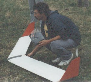
The CO2 was born. At 3.5 kilos, the weight was considerable.
But it was never a problem.
The competition season of 1988 was concluded with at lot of success. It didn't matter what weather. It didn't matter what starting type. But the real success achieved with the Co2 was of a different nature. The direction of construction combines the pleasant characteristics of the normally configured model with the sympathetic characteristics with the flying wing. As far as that is concerned, our weeks of study was starting to bear fruit. The multitude of model flyer which we handed our transmitters, could only confirm our estimates. Also with the achieved launching heights were we starting to be satisfied. We were not achieving the launching heights of the B Kader, but as we said, our winch..... To summarize with a question, what was new on the CO2?
Apart from the change in construction using two wings and not one piece wing, the negative dihedral and the winglets, nothing much was different. Or was it? Right! There was the new section. EH we named it, E for Eppler and H for Horten. We have to explain again. The way led us from the classic Eppler(Pirx) over a positive cmo profile (used IN the JIT 1) to the full symmetrical (JIT 2). The basic thought to reduce the camber to control the problem with the oscillations was found to be incorrect in f3b type flying. To add that from time to time the word flutter is mentioned in this book.
First of all, that type of appearance is not really flutter. Analyzed it consists of an oscillation in a vertical direction. as well as torsion. The point of twist should be the first third of each wing. If you look at from the trailing edge at the wing, The forces appear in the illustration below. It looks terrible doesn't it. For that reason we call it a "riesenhuber"
Just watch intensively a normal f3b start. With a medium speed including the dive at the top, the oscillations start exactly at the moment you apply elevator after diving out off the line. The induced load using a modern f3b winch is not introduced at any other point in the flight. There are people that assume that those oscillations are typical in a flying wing or more exact, for swept wings. The argument is that on the swept wing, for every bending force on the wing, the resultant force is a twisting motion at 90 degrees to the airflow. Once the oscillation is set in motion, the outer loads, e.g. winglets enforce these motions. To cure those motions it was, for example, suggested by the logo team that the spar is located to counteract those forces. You can see clearly those arguments are based to increase the twisting stiffness of the wing or trying to relocate the twisting loads into bending loads. From our experiences we know that every twisted airfoil in an swept shape or not, has those stiffness problems. Think about a thermal floater with washout and what happens when you try to dive out of a thermal at great heights. They will also flutter, not just the swept wings. (It was visible at the flying wing cup last year) Is it therefore something that is only for swept wings?
First of all we can observe that wings with washout without sufficient torsional strength will have problems. On planks which have airfoils that act like parachutes, one will probably not see those movements, But the swept wing because of its good all around capabilities can reach very quickly the limit of stability. But don't get scared about it. Those wishing to fly their swept wings similar to a conventional thermal glider will not have any problems, but with every step toward the current f3b considerations, there is no avoiding this problem. The swept wing, despite the short lever arm, absorbs the loads that a normal configured model will transfer into the fuselage. The evidence, the last B-Kader competition at which we showed the viewing public a flight with incredible oscillations, 11 normal aircraft were destroyed by broken fuselages . It becomes clear that for the dive out of the winch and the resultant forces the stability of the flying wing must be equal the complete stiffness of the normally configured aircraft of wing and fuselage together because all loadings are happening on the wing only.
 When we look back on the 1988 competition season, the whole season was without oscillations on our flying wings. Compared to our previous construction, there are two main differences. The spar was not constructed in steps, it was one continuous spar and the high amount of diagonal weave laid up in the wing.
But now back to our constructions. Despite our stiffness problems with the JIT series, it was a well flying machine. As explained before, due to the change to the Cmo=0 characteristics of the new sections, we could now go back to higher cambers and the new EH sections have helped a lot. They combine a high CG stability with a solid and comfortable separation bubble behavior. 1989 should bring us under camber of 1.5 percent. The Ca max of EH 1/9 seems to be satisfactory, we could not detect any problems with the Cmo characteristics theoretically. So what was, or is new on the CO2?
When we look back on the 1988 competition season, the whole season was without oscillations on our flying wings. Compared to our previous construction, there are two main differences. The spar was not constructed in steps, it was one continuous spar and the high amount of diagonal weave laid up in the wing.
But now back to our constructions. Despite our stiffness problems with the JIT series, it was a well flying machine. As explained before, due to the change to the Cmo=0 characteristics of the new sections, we could now go back to higher cambers and the new EH sections have helped a lot. They combine a high CG stability with a solid and comfortable separation bubble behavior. 1989 should bring us under camber of 1.5 percent. The Ca max of EH 1/9 seems to be satisfactory, we could not detect any problems with the Cmo characteristics theoretically. So what was, or is new on the CO2?
In the beginning, to write this article didn't seem to be very easy. I reported from a forth way. Meaning Lippisch, Eppler, Horton or plank philosophy. But now it is time to explain it a little clearer. Is the way in between or different? It doesn't matter, I will just try to describe it in my own words. It is a Cmo =0 section with a sweep of 18 degrees, so we can use flaps. From the flying planks we had the idea to use a continuous section. From the Eppler/Theis-Ecke, corner came the swept shape and the winglet.
With that we avoiding to think about flying just a wing. The geometry of the wing is selected that when speed flying all rudders and flaps are at 0 degrees. The outer wing has a total ca of about .15. In other words, we are trying not to use the Horten type bell shaped lift curve. We don’t use a high lift section, and weak ca type plank sections. What it is, doesn't really matter, just call it the "Glenfiddich" concept. We plan for the next year to increase the aspect ratio to increase the distance performance. We also are still working on better launch characteristics. More of this now.
At the of 1986 we introduced a new starting technique from one central hook to a v type or y type lauching system. In those days we thought that we would stop the propellor action happened so often and which had us panicking. The v tow had the advantage that the model could not be released in a skewed position to the line. The disadvantage, due to the hookup point under the profile, the model would not rotate upwards for the first 10 meters of launch. In other words we had to apply full elevator. Tests with the CO2 at the end of 1988 showed that the v type of launching wasn't necessary any more. The result was the preloading of the winch cable could be much higher at the start of the launch. There is a very safe compromise. Have a look at our detailed photographs.
(Sorry, I can't scan these real well and so they aren't here yet)BR>
With the CO2 it was possible to overcome the typical problem of the swept wing and retain the typical nice size of swept wings.
Interesting would be this model especially for the all those who do not want to fly f3b, because there is lots of other flying that can be done. For instance diving, slope racing and so on. All those people who want to build our model can build it and disregard the high weight. To all those who want to build the CO2, take some advice. Please use the best materials, that means not cheap resins or woven materials. Maybe you already know about it. The producers of those cloth weaves, prepare the tows so the weaving machines don't get ruined. This type of conditioning must be removed. Or do you want to epoxy over lacquered filaments? Interglass by 50 finish is excellent for our project.
To the resins.
Everybody should know the flexibility of resins over 50 degrees C. Use little resin, The result is that with the use of less resin and more cloth you will get a more stable wing.
For the flying.
With the CO2 you can forget about some of the specific bad behavior of some flying wings. No propellor action when launching and no stall problems any more. Just a slight tipping of the nose, into or with the wind. And think about it, the CO2 has it's basic layout for fast flying. Elevators up about 2 mm for slow flying is very acceptable. And with flaps set in 3 steps from 0- 4mm -8mm the section seems to have a very small profile drag.
So for winch start use 0 mm flap, for bungee or handstart use 4 mm and for thermal between 0 and 4 mm flap. The total lift produced by this wing is definitely better at 4 mm. All in all, we could say that the flaps act as elevators. The model climbs but doesn't bring the nose up. It just floats up. That means that activation of elevators is not necessary. And a hint for all those who have one of the modern computerized transmitters where you can, after six months of study of the manual, mix the retraction of the undercarriage with the cabin lighting, just mix flap to elevator for those tight turns. Especially on the slope, don’t be afraid to turn it by giving aileron and then full up elevator. Oh sorry, not that much. We use 10-12mm aileron and 7-9 mm elevator both directions. We don't need to use differential.
The landing.
There is a problem. First we thought we had to increase a flap in the fuselage but this was the wrong way to do it.
With that particular flap we could only land it with full up elevator and flaps at 4mm and the model still came in nose first. The best approach way for the CO2 is at 4mm flap which makes it nice and slow and stable. Just watch how the ground effect is taking place on your model.
A tip from the f3b people. If you include a bowden cable under the skin during construction, out to the tips, you can steer the rudders outside during the landing phase to act as a brake. Just try it out.
To close, lets have a look at the future. In the next season, as we already mentioned, we want to go to higher aspect ratios and more cambered sections. We envisage to use the EH 1.5/9. In Autumn 1988 we built the CO2 mini and hoped we would get some ideas about the EH 1.5/9 section. I don't know why, but the experiment was very successful. The 1600 gm 0-series model flys on the slope nearly like the Graupner Cirrus. And changes direction of flight at a 45 degree angle bank with speeds that cannot be measured with a stopwatch. All that can be said about the characteristics, is that the model is mega uncritical. Also with the electric version of this model we are looking forward to the next flying season.